Smart Soda Fridge
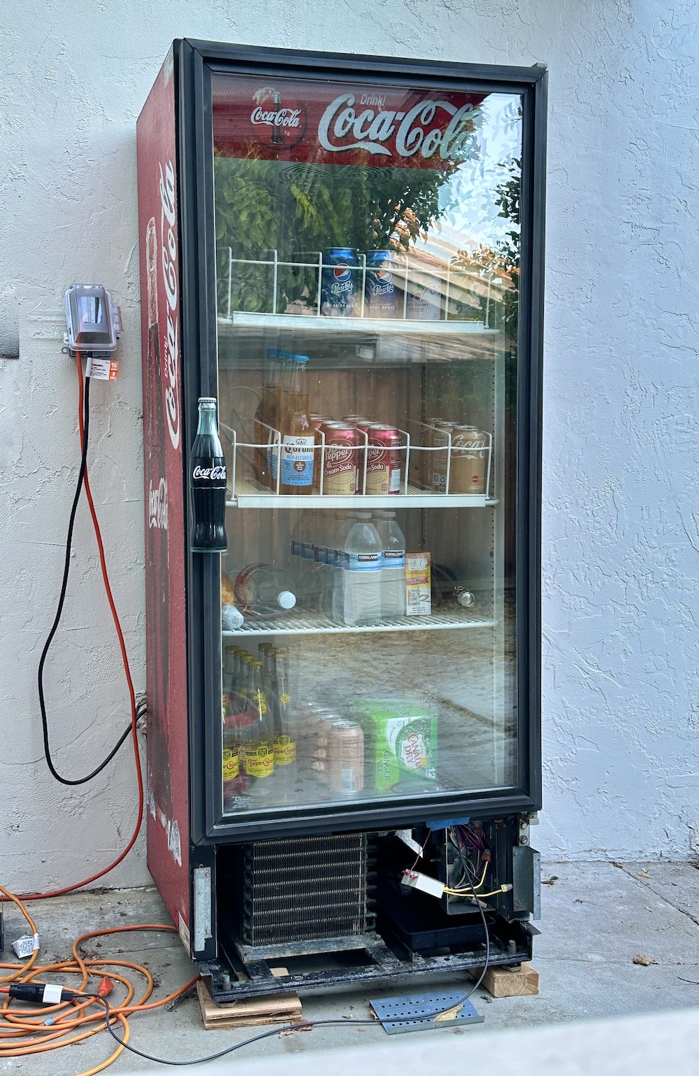
My latest irresponsible splurge totally necessary purchase was a drink refrigerator, the kind you might see in a convenience store, with a glass front and shelf racks for storing cans and bottles (the industry term for a fridge like this is apparently a “glass-door merchandiser”). I got mine on Craigslist for a mere $190, which is way less than the thousands they cost new. It seemed fine at first: the compressor and fan worked, but the power cord was damaged so deeply that bare copper was visible, and it had a mildew smell inside. So after taking it apart, replacing the power cable, and thoroughly cleaning, I plugged it in and discovered the biggest problem: the thermostat didn’t seem to be working correctly. An OEM thermostat costs over a hundred dollars, which is more than I wanted to spend on this. Being the nerd that I am, I figured I could put together something that not only would work as a functional replacement, but actually be even better: a smart thermostat I could monitor and control remotely!
I’ve been running Home Assistant for a while now, and I had vaguely heard of the ESPHome project, so I looked into it more. Turns out, it’s amazing! In a nutshell, it allows you to create your own custom “smart home” devices from the popular Espressif microcontrollers, with lots of hardware support for different boards and a variety of peripherals. You write a YAML config file that outlines what peripherals are attached and how (what pin, what bus, etc.) and ESPHome will generate, compile, and install a custom firmware blob for your device and integrate it with your Home Assistant installation. Super, super cool.
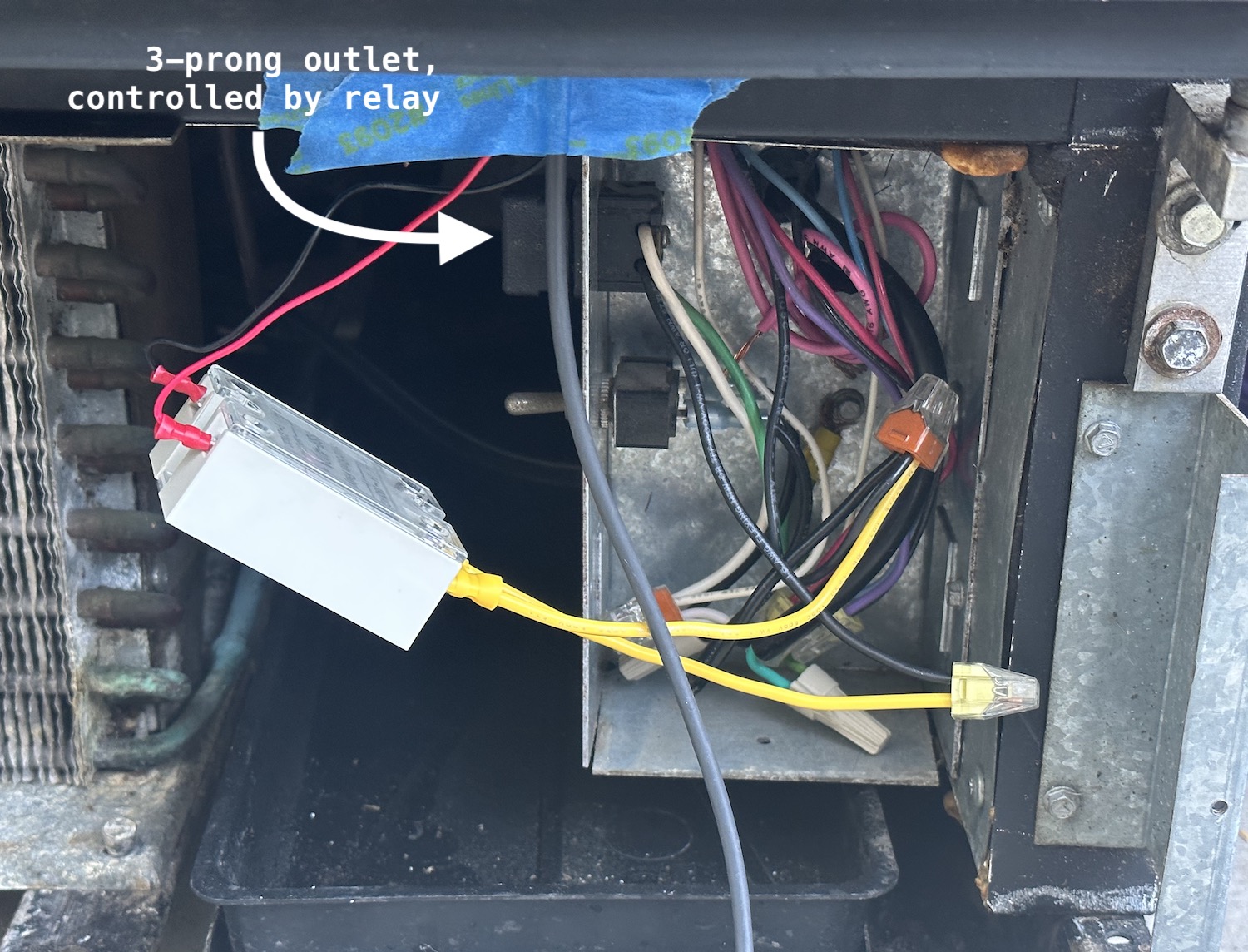
First things first, how does the thermostat work in one of these glass-door merchandisers? On my particular unit, which is a True GDM-12RF, the thermostat sits up in the top-right corner of the unit, with a long temperature probe coming out of it that snakes back into the evaporator coils. A 120-volt AC wire goes through it, and the thermostat acts as a switch for this wire: if the temperature gets warm, it closes the switch and power flows; when it gets cold, it opens the switch. Down in the base of the machine, that wire is used to power a normal 3-prong outlet which the compressor plugs into. So to create the replacement thermostat, I need to use a relay that will let me use a low-voltage signal to control the high-voltage power line.
Next I needed hardware. Here’s the list of parts I ordered from SparkFun to assemble my thermostat:
- SparkFun Thing Plus: the brains of the device, this is based on a ESP32-S2 WROOM chip that is supported by ESPHome. It’s powered with USB and supports both WiFi and Bluetooth for connecting to Home Assistant.
- TMP102 Temperature Sensor: an I2C device that connects to the main board using Sparkfun’s Qwiic connector.
- Solid State Relay: this relay can control the 120VAC power connection to the compressor, but is controlled by as little as 3VDC, which is just below the 3.3V that the ESP32 can provide.
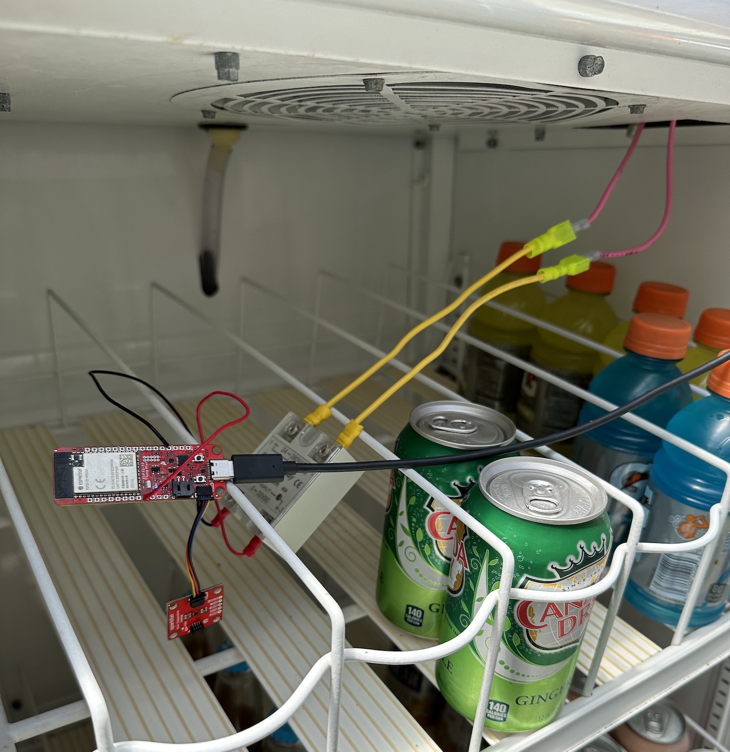
I used some spare bits of 12-gauge copper wire I had laying around to make high-voltage connectors for the relay, and soldered some thinner wires to the ESP32 to connect to the low-voltage side of the relay. I chose to put the signal wire on pin 13, which I chose because it also happens to be connected to an on-board LED, so I have a secondary way to tell if the board is trying to power the relay.
Then I needed to flash ESPHome firmware on the device. I tried doing this with a Python-based flasher tool, but couldn’t get it to work correctly, I think because I possibly was trying to use the wrong board ID. I ultimately succeeded by plugging it into my PC and using the ESPHome Web flasher, which uses WebUSB to program the device from Javascript. I have to say, even though I generally think WebUSB is a silly idea, it actually worked and was convenient in this case, so I have to admit maybe it’s not useless.
Once the board was flashed with a “blank” firmware, I could adopt it Home Assistant and configure it with the details about how it’s wired together and how I want it to behave. Below is a portion of my YAML config.
esphome:
  name: soda-machine
  friendly_name: Soda Machine

esp32:
  board: esp32-s2-saola-1
  framework:
    type: arduino

i2c:
  sda: 1
  scl: 2

sensor:
  - platform: tmp102
    id: soda_temp

switch:
  - platform: gpio
    id: soda_cooler
    pin: 13
    internal: true

climate:
  - platform: thermostat
    name: "Thermostat"
    sensor: soda_temp
    cool_deadband: 2°C
    min_idle_time: 60s
    min_cooling_off_time: 60s
    min_cooling_run_time: 60s
    cool_action:
      - switch.turn_on: soda_cooler
    idle_action:
      - switch.turn_off: soda_cooler
    visual:
      min_temperature: -25°C
For my first attempt, I put all the new components in the fridge near the top, where the original thermostat sat. This seemed to work fine, but after a while the compressor started to perform poorly: it got louder than normal, and sometimes the fan would fail to spin even when power was applied.
(In the photo below, the pink wires are the original thermostat control wire: they lead up into the compartment where the original device was installed)
My suspicion was that something was going wrong with the relay. On a hunch, I held it in my hand for a minute to warm it up, and it started performing better: I guess it doesn’t tolerate the cold very well, despite the datasheet saying it’s rated for as low as -20°C. Shifting things around a bit, I was able to move the relay outside the cold compartment, and things ran much better. I just shut the door directly on the wires: the weatherstripping around the door is flexible enough to make a passable seal over them.
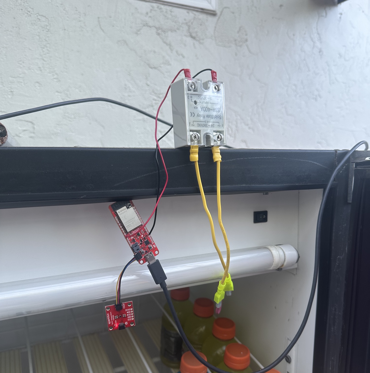
I’ve since moved the whole contraption down to the bottom of the fridge: I don’t think there’s any reason to keep the thermostat up top, especially since the device we’re trying to control is at the bottom. Right now the ESP32 is still inside the cold compartment, but only because the Qwiic cable I have isn’t long enough to keep the temperature sensor inside by itself. That should be easy enough to fix if I solder together some longer wires.
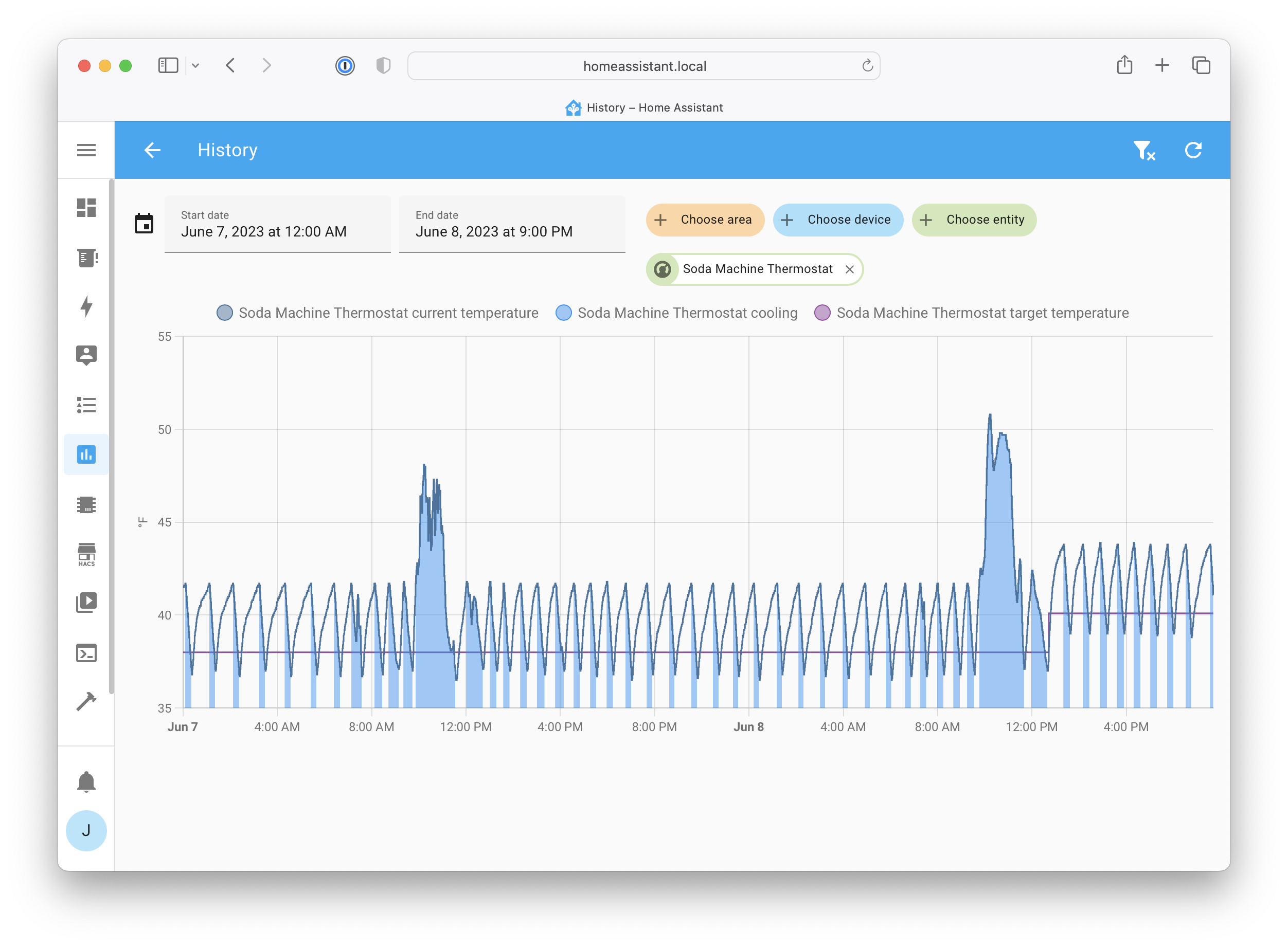
The Home Assistant integration works great: it shows up just like the Nest that controls the air in the house, and it lets me remotely monitor and set the target temperature.
The biggest to-do item is to find a way to power the ESP32 from the same wiring box as the rest of the fridge. Right now I have a separate extension cord just for the USB power adapter, but the wiring box seems to have a knockout where I could install another 3-prong outlet, which would really tidy up the installation. Once I do that, I can put the cover back on the bottom, and it’ll be completely done and can keep our drinks cold for years to come!
Working with ESPHome has been great: I feel like I have a new superpower, and now I’m looking around the house for more opportunities to build custom smart devices. Kudos to the project developers for creating such a great framework!